|
|
|
|
NERO  Projects Projects  H8 Rocket H8 Rocket |
 |
The H8 Rocket |
|
|
|
|
|
Project H8's goal is to build a rocket with
controlled fins that is able to correct disturbances in trajectory caused by cross-wind, miss-alignment etc. In
order to get familiar the the various technologies required to build such control device it will be necessary to
divide the project in phases. Each phase has to be concluded successfully before continuing with the next phase.
|
|
|
|
|
Project [Top]
[Contents] |
|
|
|
The H8 project is divided in three of phases, given below:
First phase includes model simulations of a fin
controlled rocket and the validation of these models by means of one or more flights. On these flights the fin control
is activated only after burn-out of the rocket motor. This guarantees that trajectory deviations due to failure of the
control system are minor and safe recovery is possible. Initially, only single axis control will be demonstrated, later
two and three axis control. This phase also serves to demonstrate the soundness and rigidity of inhibit- and fail-safe
mechanisms that are needed to maintain safety under all practical circumstances. |
|
|
  |
Read an article about the aerodynamic design. |
|
|
|
Second phase includes closing the loop in the fin
control system. Flights will have to demonstrate that certain commanded attitudes c.q. orientations can be acquired and
maintained during the flight. An example is stabilisation of roll rate after lift-off. During the second phase fin
control is active only after burn-out of the motor.
Third phase implies that the control system is active
during the propelled phase, instead of after burn-out. This makes it possible to perform corrections for cross-wind
influence, and as a result of that also a more predictable trajectory, and a higher probability of safe recovery. |
|
|
  |
Take a look at the pictures of the H8. |
|
|
|
Design [Top]
[Contents] |
|
|
|
The following subsystems are part of the H8: |
|
Rocket engine: The H8 will be boosted by
a MEROC composite motor, type Penta-1000. This motor has a relatively short burning time of only 1,2 seconds in
combination with a moderate total impulse of approximately 1040 Ns. It is qualified in various flights of the U-series
rockets and has never failed so far. |
|
Recovery system: This is based on the proven design of other Haarlem
rockets. A pyro bolt ejects a lateral hatch and releases a cruciform parachute. Descent velocity on the parachute is
10-15 m/s. The pyro bolt is activated by the timer output of the newly developed R-DAS module from AED (see web site
information). Lift-off is detected using a break wire and/or by means of the build-in acceleration sensing function of
the R-DAS module. Follow the link to learn more about the parachutes of the Haarlem rockets. |
|
Data acquisition: The Data acquisition module is provided with three
external gyro sensors of the type Murata ENC-05, These have a range of 90 deg/s which is more than the calculated
worst-case angular velocity about any axis of the rocket, during the fin control experiment. The R-DAS module samples
standard acceleration and pressure, which allows reconstruction of the major trajectory data (velocity and altitude as
function of time). Furthermore, relevant parameters in the fin controller such as battery voltage and statuses will be
measured. |
|
Fin controller experiment and aerodynamics: Single pitch axis control
is performed using a pair of canards (front fins), driven by step motors. The motor control circuit is provided with a
micro controller that commands a sequence of deflection angle set points as a function of time. Follow the link to
learn more about the canard controller, associated circuit and phase one experiments. |
|
|
|
 |
|
|
Canards |
|
|
Gyro's |
|
|
Parachutes |
|
|
Pyro systems |
|
|
Penta motor |
|
|
|
|
|
Model [Top]
[Contents] |
|
|
|
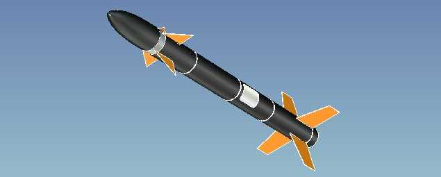
For educational purposes only, we developed a 3D model of the H8. This is only a rough
model, but we have the intention to refine it in future. |
|
|


180KB |
Download the VRML-model of the H8. |
 - - |
Download your VRML-viewer. |
 |
Look at the H8 VRML-model. |
|
|
|
 |
|
|
|
De H8a [Top]
[Contents] |
|
|
|
The H8 has flown on the NLC-3 on 11 June 1999. The flight of the H8a
was only partly a success. We recovered data, but the parachute compartment, the tail fins and one of the step-motors
where badly damaged by the "landing". During the flight an experiment with canard fins was executed. With the
bare eye we could see the H8 change his angle of attack. The movements of the rocket where measured by means of three
gyroscopes. Download the data-file below, to see what we measured. |
|
|
  - - |
read the report of the H8a flight |
|
|
 
403KB |
Download the H8a R-DAS data file |
 - - |
Download the viewer fore the H8a R-DAS data file. |
 - - |
Read more about the Rocket Data Acquisition System (R-DAS). |
|
|
|
|
|

