Characterization of the Murata solid-state gyroscope
|
|
Since ten years the company Murata from Japan produces compact low-budget solid state gyroscopes, to be used for picture stabilization in video camera's and in car navigation systems. Because of their very small size these gyroscopes are ideal for application in amateur rockets. Last year the price of these devices has dropped dramatically and therefore made it possible to use this device in amateur rockets. |
| Category | Subject | Specification |
| Power supply | Voltage | 5 V |
| Current consumption | max. 5 mA | |
| Output | Full scale range | +/- 90 degree/sec |
| Sensitivity | 1,11 mV per deg/sec (+/- 20%) | |
| Bias | 2,3 V | |
| Linearity | Linearity | 5 % max |
| Temperature | Operational range | -5 to 75 degreesCelcius |
| Drift by above | +10% tot -20% van de volle schaal | |
| Physical data | Mass | 2,7 gram |
| Size | 22 x 9 x 8 mm3 |
The Murata ENC-05EA is a rate gyro: the output signal is proportional to the angular velocity about the (single) input axis.Other characteristics of the sensor for which we lack information are its cross sensitivity, i.e. the sensitivity for rotation about axes perpendicular to the input axis, and its thermal drift as a function of temperature.
2.
The vibration test setup consists of a heavy 300 W bass loudspeaker which has been transformed into a shaker facility for small masses. In the centre cone of the speaker a polyurethane foam platform has been glued, providing a mounting plane for a sensor head and instrumentation. The instrumentation on the platform consists of a small accelerometer mounted on a PU foam cube (2x2x2 cm3) together with the sensor under test and a conditioning amplifier. The bass speaker is driven by a 60 W audio amplifier which has a sine-generator at its input. The level of vibration is measured by putting the accelerometer signal on an oscilloscope. By observing the gyro sensor output simultaneously the disturbance of the sensor can be determined. During this test the sensor is not subjected to rotation, i.e. angular velocity about the input axis was zero, and the vibration axis is perpendicular to the input axis. The sensor pcb is provided with an AC-coupled conditioning amplifier suggested by the manufacturer. The amplifier has a bandwidth of approximately 1 kHz. The output signal of the sensor after the conditioning amplifier is 11,5 mV per deg/sec.
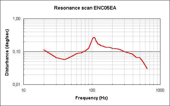
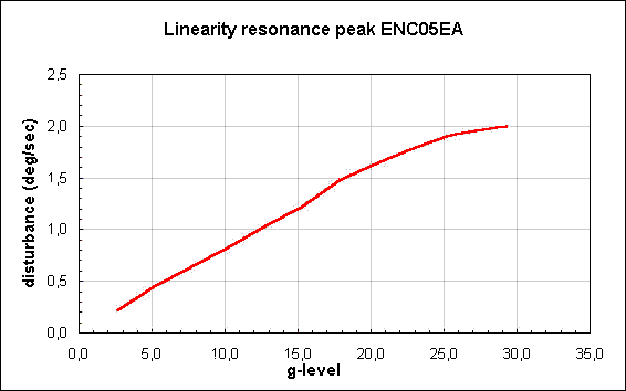
With this set-up two experiments have been performed: (1) A resonance scan from 20 Hz to 650 Hz at a constant sine vibration level of 2,5 G amplitude. The intention was to determine for which frequencies the sensor is most sensitive. The resonance frequency is supposed to be the frequency for which the sensor is considered the most susceptible to vibration damage. (2) A linearity measurement at the frequency of resonance. The intention is to determine the highest level of vibration that the sensor can be subjected to, without causing damage.

Figure 1 - Resonance scan ENC05EA
A low Q-factor resonance is observed at a frequency of 109 Hz (+/-10 Hz). The amplitude of the disturbance varies between 0,06 and 0,26 deg/sec, which is less than 1 promille of the full scale signal of the gyroscope. The result of the linearity measurement is shown in figure 2.

Figure 2- Liniarity resonance peak ENC05EA
The amplitude of the disturbance is practically proportional to the amplitude of the vibration, and this result is also reproduceable. Up to a sine vibration amplitude of 29 G remains functioning. For this frequency this G-level is also the limit of the test set-up. The disturbance at this level is still less than 2 deg/sec. Taking 30 seconds for each step increase in G-level, the overall duration of the linearity test was approximately 5 minutes. The functionality of the sensor is checked by means of a simple test: the sensor is rotated about its input axis, by hand, and the order of magnitude of the output signal is determined. When "measured" this way, no difference is observed between the behavior of the sensor before and after the vibration tests. Of course it is possible that the vibrations causes some subtile damage to the sensor, however that can only be determined with a more accurate rotation- or pendulum set-up..
These measurements have been performed in the summer of 1998. It is intended to continue the experiments by subjecting the sensor to random noise and shocks, and to measure the temperature drift coefficient and cross-axis-sensitivity in a calibration set-up. If anyone has other sources of information on the environmental characteristics of these sensors I would be pleased to know.